Quality Power Amplifiers
Kuhne is your partner for process and measurement technology in the high frequency and microwave sector. The development as well as engineering and also our production of the components takes place under one roof
Browse our products
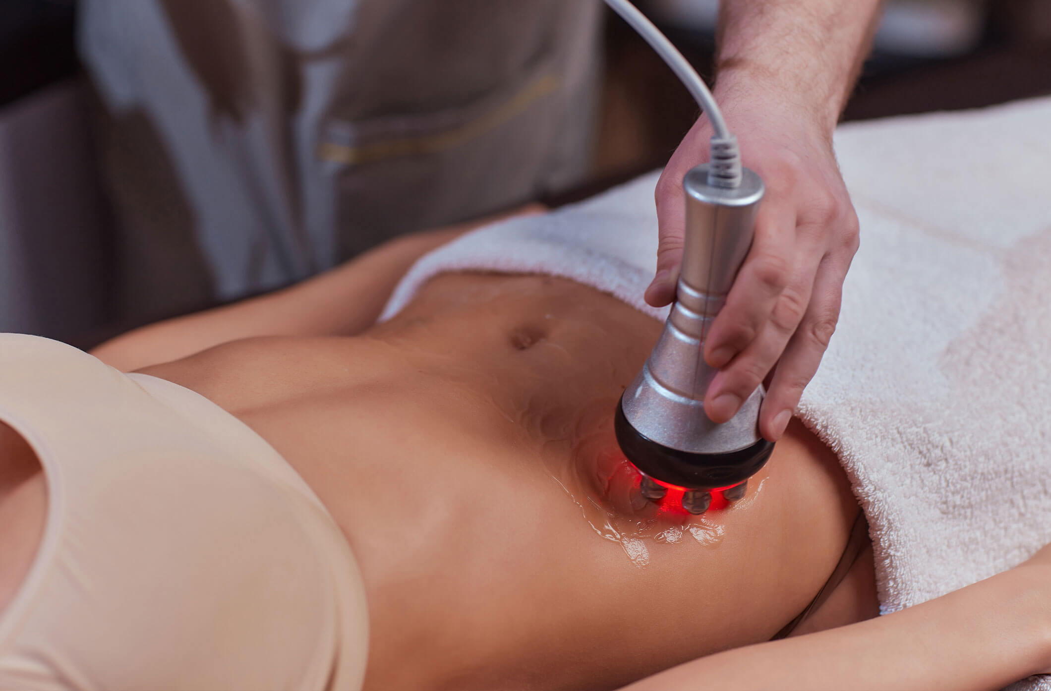
RF in Medicine
Microwave Generator 2.45 GHz - Can be used for propagation tests of electromagnetic waves, EMC tests, plasma generation and various other applications.
Browse our products